Systems Exploration, Engineering, and Design (SEED) Laboratory
SEED Lab is a semester-long design and build activity centered around a challenge problem that varies from year to year. Solving this problem requires the design and prototyping of a complex system and utilizes concepts from multiple electrical engineering courses. Students work in intra-disciplinary teams, with students focusing a particular subsystem.
Funding for the SEED lab has been generously provided by Epilog Laser
Course Objectives
- Design and debug integrated systems as an intra-disciplinary team.
- Design experiments and gather data to solve engineering problems and/or demonstrate performance of sub-systems or systems.
- Predict the performance of a designed system and verify their predictions experimentally.
- Work effectively in intra-disciplinary teams to solve engineering problems.
- Engage in reflective learning and demonstrate an ability to engage in life-long learning.
Course Features
- The project requires expertise in more than one area of EE
- Students choose specialization and work in groups to complete the project
- The project requires multiple systems to be integrated
- Success requires finding and utilizing information about subsystems, along with building, testing and debugging hardware and software
- Project design includes the development and validation of system and component models
- Part of the course grade depends on the performance of the built system at a series of demonstrations
- Undergraduate Course Assistants provide guidance and assistance
SEED Lab Projects
AY 21/22
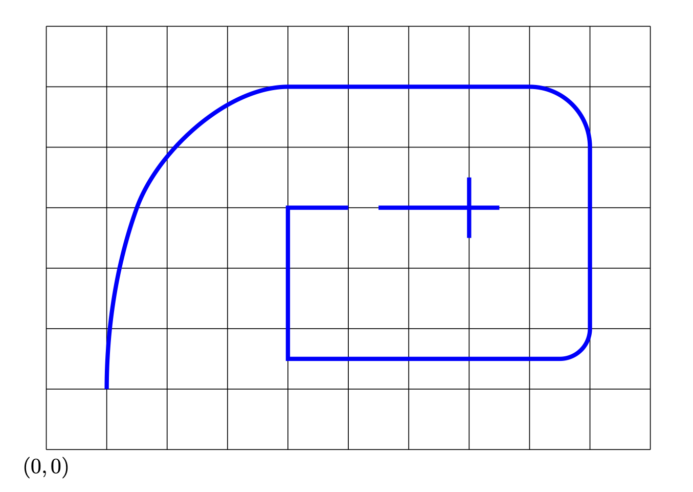
Warehouse robots need to be able to follow appropriate paths in order to navigate around their workspace. Once option for defining a path is to use a colored line. In this challenge, you will design and build a robot that can follow a path defined by 1″ wide blue painter’s tape. The robot must be able to keep its rotational center within 1 foot of the tape at all times. The path to be followed will be approximately as given by the image below. The spacing of the grid in this image is one foot. The robot will be placed at coordinate (0,0) facing away from the tape, so it will have to first rotate to locate it. The robot’s success will be determined by how far it is able to make it down the path, and the speed at which it travels. Note that there is a break in the tape at (5,4). The robot will have to successfully pass over this break. The robot should stop when it reaches the crossed tape at (7,4).

AY 19/20 and AY 20/21
A challenging yet promising arena for robots is for search and rescue in dangerous areas. This provides the inspiration for this year’s challenge project: as a team, you will build and program a mobile robot that is able to explore an area that is known only as the robot starts to explore. In this challenge, six beacons of your design will be placed on the ground to denote the exploration area. The robot must be able to traverse a path around the outside of these beacons, but cannot stray too far away, or cut inside the beacons. That is, the robot must complete a circuit that contains the the area defined by straight lines drawn between beacons, but cannot go more than 1.5 feet away from this area at any time.
The spring semester had an extra challenge as classes when remote in the middle of March. Each team selected one person to take all of the equipment, and the other team members worked on the Raspberry Pi and Arduino by installing the Arduino IDE on the Raspberry Pi and using a VNC virtual desktop to work on the Raspberry Pi remotely. Teams were already using tools like Github to coordinate their work, but Zoom was essential for team meetings and debugging. Because of these extra challenges, the final project objective was changed to finding a single beacon and circumnavigating around it. The teams were able to demonstrate remotely using Zoom, with some of the demos shown in the video below
AY 18/19
As a team, you will build and program a mobile robot that is able to follow a prescribed path. In order to define the path, you will build beacons that the robot can view using a camera. The path will be defined as points on an x/y grid (with units of feet) that the robot must visit in order. You can place as many or few of your beacons as you wish on the floor in order for the robot to execute this path.
AY 17/18